
 EN
EN
 EN
EN ZH
ZH IT
IT ES
ES TH
TH TR
TR JA
JA PT
PT KO
KO RU
RU FR
FR DE
DE AR
AR
 Home > News Center > Industry news > How to Select a Planetary Reducer for a Robotic Arm Actuator
How to Select a Planetary Reducer for a Robotic Arm Actuator
In robotic automation, the transmission system determines much more than the final output speed. It affects positioning accuracy, repeatability, payload capacity, mechanical stiffness, energy consumption, noise, service life, and the overall size of the robot joint. For this reason, selecting a gearbox for a robotic arm should not be treated as a simple ratio-matching exercise.
A planetary reducer is one of the transmission technologies frequently considered for robotic applications because it can provide high torque density, compact dimensions, low backlash, and efficient power transmission. When correctly matched with a servo motor and control system, it can form the mechanical core of a precise robotic joint.
For system designers, robot integrators, automation companies, and equipment manufacturers, the key question is not simply whether a planetary gearbox can be used in a robotic arm. The more useful question is whether its accuracy, torque capacity, mechanical interface, thermal characteristics, and service life are suitable for the specific robotic arm actuator being developed.
Liangzhi Joint focuses on drive integration solutions, including robotic joint modules and high-precision transmission components. Supported by a shareholder team with more than 20 years of industry experience, the company established its current business in 2024, with R&D capabilities in Hangzhou and Shenzhen and production bases in Zhejiang and Dongguan. Its product development covers high-precision planetary reducers and related robotic transmission solutions, with maximum accuracy reaching 1 arcminute and more than 30 national patents.
This article explains the practical considerations behind planetary reducer selection for robotic arms, including gear ratio, torque, backlash, stiffness, motor matching, installation, load conditions, and application-specific requirements.
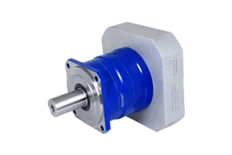
What Is a Planetary Reducer?
A planetary reducer is a compact gear transmission consisting primarily of a sun gear, multiple planetary gears, a planet carrier, and a ring gear. The gears operate around a common central axis, creating a coaxial transmission structure.
Unlike a conventional spur gear arrangement that may require several stages positioned along different axes, a planetary gear mechanism distributes load among multiple planetary gears. This architecture allows a relatively small gearbox to transmit substantial torque.
The basic operating principle is straightforward. The motor drives one element of the planetary gear set, while another element acts as the output and the remaining element is fixed or otherwise controlled. By changing the arrangement, engineers can achieve different speed reduction ratios and torque characteristics.
For robotic applications, the coaxial structure is particularly useful. A robotic arm joint usually has strict dimensional constraints because the gearbox, motor, encoder, bearings, brake, wiring, and housing must fit into a limited space. A transmission that can deliver high torque without requiring a large offset structure can simplify joint design.
A planetary reducer can also be configured with multiple gear stages. Higher reduction ratios are generally achieved by combining stages, although increasing the number of stages can influence efficiency, size, heat generation, and mechanical complexity.
The important point for robotic applications is that a planetary reducer should be evaluated as part of a complete drive system rather than as an isolated gearbox.
Why Planetary Transmission Is Used in Robotic Arms
Robotic arms have requirements that are different from many conventional industrial machines. A conveyor drive, for example, may operate at a relatively constant speed and experience predictable loading. A robot joint can repeatedly accelerate, decelerate, stop, reverse direction, and hold a payload at different positions.
This creates several requirements for the transmission.
First, the gearbox must withstand repeated dynamic loads. Second, it needs sufficient torsional stiffness to maintain positioning performance. Third, backlash must be controlled because excessive clearance can become visible as positioning errors when the direction of rotation changes.
Size is another consideration. A large gearbox can increase the mass of a robot joint, which then increases the torque required from upstream joints. This creates a cascading effect throughout the robotic arm.
For example, if a wrist actuator becomes unnecessarily heavy, the shoulder and elbow joints must move both the payload and the additional mass of the wrist assembly. The result can be higher motor requirements, greater energy consumption, and lower dynamic performance.
A compact planetary transmission can therefore contribute to overall system optimization, provided its mechanical characteristics match the application.
Understanding the Role of the Robotic Arm Actuator
The robotic arm actuator is the unit that converts electrical control signals into controlled mechanical movement. Depending on the robot architecture, an actuator may include a servo motor, gearbox, encoder, brake, bearings, housing, drive electronics, and mechanical interfaces.
In many modern robotic systems, the actuator is increasingly treated as an integrated module rather than a collection of unrelated components.
The transmission is responsible for reducing motor speed and increasing output torque. The motor may rotate at several thousand revolutions per minute, while the robot joint requires much slower movement with substantially higher torque.
Suppose a servo motor operates at 3,000 rpm while the joint needs approximately 30 rpm. A theoretical reduction ratio of 100:1 would bring the motor speed down to the required range. However, selecting a 100:1 gearbox based only on this calculation would be insufficient.
The engineer must also consider:
Continuous output torque
Peak output torque
Acceleration and deceleration
Duty cycle
External radial loads
External axial loads
Emergency stop conditions
Backdriving requirements
Positioning accuracy
Repeatability
Torsional stiffness
Thermal operating conditions
Expected service life
Mounting dimensions
Motor flange compatibility
Encoder arrangement
This is why gearbox selection should begin with the actual motion profile rather than simply starting with a preferred gear ratio.
How Gear Ratio Should Be Selected
Gear ratio is one of the first specifications considered during actuator design.
The fundamental relationship is:
Output speed = Motor speed ÷ Reduction ratio
If a motor runs at 3,000 rpm and a 50:1 reduction is used, the theoretical output speed is approximately 60 rpm before considering operating limitations and efficiency.
The torque relationship is similarly important:
Output torque ≈ Motor torque × Reduction ratio × Efficiency
This is a simplified calculation, but it demonstrates why a reducer allows a relatively small motor to produce much higher output torque.
However, a higher ratio is not automatically better.
Increasing the reduction ratio can increase output torque while reducing output speed. It may also introduce additional gear stages, which can influence efficiency and thermal performance. For a robot that requires rapid movement, excessive reduction can restrict the maximum joint speed.
Therefore, the ratio should be selected from the required output speed, motor operating range, torque demand, and motion profile.
For example, a pick-and-place robot may prioritize acceleration and high cycle frequency, while a heavy-duty articulated robot may place greater emphasis on continuous torque and holding capability.
A collaborative robot may have additional requirements involving compactness, backdrivability, collision detection, and human-machine interaction.
There is no universal reduction ratio for all robotic joints.
Continuous Torque and Peak Torque Are Different
One of the most common mistakes in transmission selection is comparing only the nominal motor torque with the nominal gearbox torque.
Robotic motion is dynamic. A joint may operate at a moderate torque during normal movement but experience much higher torque during acceleration, deceleration, direction changes, or collision events.
For this reason, both continuous torque and peak torque should be evaluated.
Continuous torque refers to the output torque that the transmission can handle during sustained operation under specified conditions.
Peak torque refers to the higher torque that can be tolerated for a limited duration.
The actual motion profile determines how often the gearbox experiences these loads. A short peak repeated thousands of times per day may have a different effect from an occasional peak.
Engineers should therefore provide the gearbox supplier with realistic operating information, including:
Motor rated torque
Motor peak torque
Operating speed
Reduction ratio
Acceleration time
Deceleration time
Cycle time
Number of cycles
Payload
Arm length
Joint orientation
External forces
Ambient temperature
This information allows the transmission to be evaluated under actual operating conditions rather than a simplified static calculation.
Backlash and Positioning Accuracy
Backlash is particularly important in robotic transmission systems.
Backlash refers to the angular clearance between mating gear components. A small amount of clearance is necessary for proper operation in many gear systems, but excessive backlash can reduce positioning performance.
Imagine a robot joint moving clockwise and then immediately reversing direction. If the transmission contains significant backlash, the motor may rotate through a small angle before the output shaft responds in the opposite direction.
In applications requiring precise path tracking, this dead zone can become a serious problem.
For this reason, high-precision robotic transmission systems require controlled manufacturing tolerances, accurate gear geometry, proper assembly, and appropriate preload or bearing arrangements.
A planetary reducer designed for general industrial equipment may not provide the same performance as a high-precision transmission intended for robotic motion.
When comparing products, buyers should not look only at a marketing statement such as "high precision." It is more useful to ask for a defined backlash or positioning specification and understand the test conditions under which it was measured.
For high-precision applications, Liangzhi Joint develops planetary reducer products with accuracy reaching as low as 1 arcminute. The actual suitability of a specific model still depends on the complete actuator configuration and application requirements.
Torsional Stiffness Matters in Robot Joints
Backlash is only one part of transmission accuracy.
Torsional stiffness describes how much the transmission twists under applied torque. A gearbox can have low backlash but still experience measurable elastic deformation when a substantial load is applied.
Consider a robot arm holding a heavy payload at an extended position. The output torque can become significant because of the moment created by the distance between the payload and the joint axis.
If the transmission has insufficient torsional stiffness, the output position may change slightly as the load changes. This can influence robot path accuracy and settling time.
High torsional stiffness is especially important for:
Precision assembly
Machining
Laser processing
Inspection
Vision-guided positioning
Welding
High-speed pick-and-place
Semiconductor handling
Laboratory automation
When evaluating a planetary reducer for these applications, engineers should request stiffness data rather than relying solely on backlash specifications.
The Relationship Between Payload and Joint Torque
Payload weight alone does not determine the torque requirement of a robotic joint.
The distance from the payload center of gravity to the joint axis is equally important.
A simplified static relationship is:
Torque = Force × Lever arm
If a payload weighs 10 kg, the gravitational force is approximately 98.1 N under standard gravity. If the center of gravity is 0.5 m from the joint axis, the static gravitational torque is approximately 49.05 N·m.
This is only a simplified example. Real robotic joints may experience additional torque caused by:
Acceleration
Deceleration
Inertia
Gravity
Friction
Cable forces
Tool forces
External process loads
Dynamic changes in payload
Therefore, gearbox selection should consider the worst-case operating position rather than only the average load.
The same payload can create dramatically different joint requirements depending on where it is positioned.
Planetary Reducer vs. Other Gearbox Technologies
Planetary reducers are not the only transmission option for robotic arms. Harmonic drives, cycloidal reducers, bevel gear systems, worm gearboxes, and other architectures are also used.
The correct choice depends on the application.
Planetary Reducers
Planetary systems are attractive when the design requires a combination of compact size, high torque density, efficiency, speed capability, and precision.
They are commonly considered for servo-driven automation, robotic joints, AGVs, precision machinery, and other motion-control equipment.
Their coaxial structure can simplify motor and output alignment.
Harmonic Reducers
Harmonic drives are widely associated with robotic joints requiring very low backlash and high reduction ratios in compact packages.
They can be especially useful in applications where precise positioning and compact joint construction are critical.
However, designers should consider torsional stiffness, shock loading, service conditions, efficiency, and cost when making a comparison.
Cycloidal Reducers
Cycloidal transmission can provide high torque capacity and strong shock-load resistance. It is often considered for heavy-duty robotic applications and industrial equipment.
The physical architecture, speed, noise, size, and precision characteristics should be evaluated against the specific joint requirements.
Worm Gearboxes
Worm gears can provide high reduction ratios and may offer self-locking characteristics under certain configurations.
However, efficiency and thermal performance can be concerns, particularly when compared with more efficient transmission architectures.
The important lesson is that gearbox selection should be based on application requirements rather than choosing a technology simply because it is widely used.
Matching the Reducer With the Servo Motor
A gearbox and motor should be treated as a matched system.
The motor determines available speed and torque. The reducer changes these characteristics at the output. If the combination is poorly matched, the system may fail to deliver the required performance even when both individual components appear adequate.
Motor selection should consider:
Rated power
Rated speed
Peak torque
Rotor inertia
Encoder resolution
Brake requirements
Motor dimensions
Flange specification
Shaft diameter
Control mode
The gearbox must then be checked for compatibility.
The motor inertia is particularly relevant in high-dynamic applications. The transmission changes the effective inertia seen by the motor, and the complete servo system needs to be tuned accordingly.
A suitable robotic arm actuator therefore requires mechanical compatibility as well as electrical and control compatibility.
Encoder Integration and Position Feedback
Modern robotic joints typically depend on position feedback.
An encoder can be mounted on the motor side, output side, or both, depending on the control architecture.
A motor-side encoder measures motor rotation, but the actual joint position can be affected by gearbox backlash and elastic deformation. An output-side encoder can provide more direct information about the final joint position.
The appropriate configuration depends on the accuracy requirements and control strategy.
For high-precision robotic applications, engineers should consider how the encoder is mechanically integrated into the actuator and whether the gearbox structure introduces any error between motor position and output position.
This is one reason integrated robotic joint modules can be attractive to system developers. Instead of separately sourcing a gearbox, motor, encoder, housing, and other components and then solving the mechanical interfaces internally, an integrated module can reduce engineering workload.
Why Mechanical Interfaces Matter
Even a high-performance reducer can be difficult to use if its mechanical interfaces do not match the customer's design.
Important interface dimensions include:
Motor mounting flange
Input shaft diameter
Output flange
Bolt pattern
Pilot diameter
Overall length
Housing diameter
Cable clearance
Bearing arrangement
Mounting orientation
For robot builders, dimensional compatibility can be just as important as torque rating.
A gearbox that requires major structural modifications can increase development time and tooling costs.
Standardized interfaces can simplify replacement and integration, while customized interfaces may be necessary for specialized robotic platforms.
When discussing a new project with a transmission supplier, it is useful to provide a mechanical drawing or CAD model at an early stage.
Radial and Axial Loads Must Not Be Ignored
Gearbox torque is only one part of the mechanical load.
Robot joints can experience radial and axial forces through tooling, payloads, arm geometry, and external process forces.
For example, a gripper may create an offset load that generates a bending moment at the output flange. A welding tool can introduce process forces into the robot wrist. A machining robot may experience substantially higher external loads than a simple material-handling application.
The gearbox's internal bearings and output structure must therefore be evaluated against the actual load.
A transmission rated for a certain output torque does not necessarily mean that its output bearing arrangement can tolerate every possible radial or axial loading condition.
This distinction is important when designing a robotic arm actuator.
Service Life and Duty Cycle
Gearbox life depends on more than calendar time.
A robot operating eight hours per day at low load is not equivalent to a robot operating 24 hours per day at high load and frequent acceleration.
Service-life calculations should take into account:
Load level
Speed
Duty cycle
Operating temperature
Lubrication
Shock loads
Reversals
Installation accuracy
Maintenance conditions
For high-cycle automation, the number of motion cycles can become an important design parameter.
A transmission supplier should be able to discuss expected service life based on the application's actual load and speed profile.
For procurement teams, this is more useful than selecting a product based solely on a generic "long life" claim.
Thermal Considerations
Efficiency affects temperature.
Every mechanical transmission produces some energy loss, which becomes heat. As the reduction ratio, load, speed, and duty cycle increase, thermal management becomes more important.
Excessive operating temperature can affect lubricant performance, sealing components, bearings, and gear life.
In a compact robotic joint, thermal management can be challenging because the motor and gearbox may be enclosed in a small housing with limited airflow.
Engineers should therefore consider:
Ambient temperature
Continuous output torque
Input speed
Duty cycle
Gearbox efficiency
Housing dimensions
Heat dissipation
Lubricant specifications
A gearbox that performs well during a short laboratory test may behave differently during continuous production operation.
For this reason, thermal validation under realistic cycle conditions is recommended before mass deployment.
Lubrication and Maintenance
Lubrication directly affects gear and bearing performance.
The lubricant must be compatible with the gearbox design, operating temperature, speed, load, and sealing system.
In many robotic systems, reducing maintenance is a major objective. The robot may operate inside an automated production line where accessing a joint is difficult.
When selecting a planetary reducer, users should clarify:
Lubricant type
Lubricant quantity
Factory lubrication status
Recommended replacement interval
Operating temperature range
Seal requirements
Maintenance procedures
If the gearbox is integrated into a sealed robotic actuator, the lubrication strategy should be considered during the initial mechanical design rather than after the prototype has been built.
Installation Accuracy Influences Performance
A precision gearbox cannot compensate for poor installation.
Misalignment between the motor shaft and gearbox input, incorrect mounting, uneven flange surfaces, excessive bolt tightening, or improper bearing loading can influence operating performance.
Installation should follow the supplier's specified tolerances and procedures.
The mounting surface should be clean and sufficiently rigid. Shafts and pilot surfaces should be properly aligned. Couplings should be selected according to the expected torque and misalignment.
For precision robotic equipment, assembly quality can have a direct impact on the final positioning performance of the entire system.
This is particularly relevant when a robot builder purchases reducers as individual components and integrates them into a custom actuator.
Designing a Compact Robotic Joint
Space is often limited inside a robotic arm.
The joint housing may need to accommodate the motor, planetary reducer, encoder, brake, bearings, connectors, cables, and structural components.
A compact transmission can make it easier to design a smaller joint, but compactness should not be evaluated independently from load capacity.
A smaller gearbox may have limitations in thermal dissipation or bearing capacity. Conversely, an oversized gearbox can increase joint weight.
A practical design process should therefore balance:
Torque density + dimensional envelope + precision + stiffness + thermal performance + service life
The best solution is rarely the smallest possible gearbox. It is the smallest gearbox that reliably meets the complete set of performance requirements.
When an Integrated Joint Module Makes Sense
For companies developing robotic equipment, integrating individual components internally can provide maximum design flexibility. However, it also requires engineering resources.
The team must solve:
Motor selection
Gearbox selection
Encoder integration
Bearing arrangement
Housing design
Brake integration
Cable routing
Thermal management
Assembly
Calibration
Testing
An integrated joint module can reduce some of this workload by combining several functions into one engineered unit.
This can be particularly useful for companies developing robotic platforms with multiple joint sizes or product variants.
Instead of redesigning every actuator from the beginning, the engineering team can evaluate a modular product family and adapt the mechanical and control interfaces to the robot architecture.
For OEM equipment developers, this approach can shorten development cycles and reduce integration risks.
Application Examples
Industrial Articulated Robots
Industrial articulated robots typically require high repeatability, reliable continuous operation, and sufficient torque for handling tools or payloads.
The transmission must tolerate frequent acceleration and deceleration while maintaining stable positioning.
For these systems, engineers should pay close attention to continuous torque, peak torque, stiffness, backlash, thermal performance, and service life.
Collaborative Robots
Collaborative robots place strong emphasis on compactness, lightweight construction, precise movement, and controlled interaction.
The actuator design can influence the overall robot weight and dynamic behavior.
A compact planetary reducer may be considered when its torque, precision, stiffness, and safety-related requirements align with the application.
Pick-and-Place Systems
High-speed pick-and-place equipment often requires rapid acceleration and short cycle times.
In this environment, speed and inertia become particularly important.
Selecting an excessively high reduction ratio may provide more torque than necessary while limiting joint speed. The transmission should instead be matched to the motor and required motion profile.
Machine Tending Robots
Machine tending applications can involve repeated loading and unloading of parts, frequent motion reversals, and exposure to industrial environments.
The transmission should be selected for the expected cycle count and environmental conditions.
Inspection Robots
Inspection applications may require precise positioning for cameras, sensors, probes, or measurement equipment.
Low backlash and adequate stiffness can be important because even small angular deviations can affect measurement position.
Mobile Manipulators
Mobile robots with articulated arms have additional weight constraints.
The actuator must deliver sufficient joint torque without adding unnecessary mass.
In this case, torque density becomes a major selection parameter because every additional kilogram can influence the mobile platform's energy consumption and stability.
A Practical Selection Workflow
A systematic selection process can prevent many problems during prototype development.
Step 1: Define the Robot Motion
Document the required joint speed, acceleration, travel range, cycle time, and operating frequency.
Do not start with the gearbox catalog. Start with the robot's motion requirements.
Step 2: Calculate the Load
Determine payload, arm length, center of gravity, external forces, and expected dynamic loads.
Calculate the required output torque for both normal and peak operating conditions.
Step 3: Determine the Motor
Select a motor based on the required speed, torque, inertia, power, and control requirements.
Step 4: Select the Reduction Ratio
Use the motor speed and required joint speed to establish a suitable ratio range.
Then verify that the selected ratio provides adequate output torque without compromising the required joint speed.
Step 5: Check Precision
Review backlash, positioning requirements, repeatability, torsional stiffness, and encoder configuration.
Step 6: Check Mechanical Loads
Verify radial load, axial load, bending moment, and output flange requirements.
Step 7: Check Thermal Performance
Evaluate continuous operation under the actual duty cycle.
Step 8: Verify Mechanical Integration
Compare dimensions, mounting interfaces, shaft geometry, connectors, and housing requirements.
Step 9: Conduct Prototype Testing
Run the actuator under realistic motion profiles instead of testing only at no-load conditions.
Step 10: Confirm Production Requirements
Before finalizing the supplier, evaluate consistency, quality control, technical support, delivery capability, and customization options.
This workflow is more reliable than selecting a reducer based on one specification such as maximum torque.
What Should Buyers Ask a Reducer Supplier?
A procurement team should prepare a technical checklist before requesting quotations.
Useful questions include:
What is the rated output torque?
What is the allowable peak torque?
What is the maximum input speed?
What reduction ratios are available?
What is the backlash specification?
What is the torsional stiffness?
What radial and axial loads can the output support?
What is the expected service life under the proposed duty cycle?
What lubrication is used?
What is the operating temperature range?
What motor interfaces are available?
Can the output flange be customized?
Can the gearbox be integrated into a robotic joint module?
What testing is performed before shipment?
What technical documents are available?
What is the standard delivery cycle?
Can prototypes be supplied before volume orders?
These questions help transform a general purchasing discussion into an engineering evaluation.
Why Delivery Time Can Affect Robot Development
Transmission components are often critical-path components in robot development.
A prototype cannot be fully assembled if the gearbox is unavailable. Delays in mechanical components can consequently delay electrical integration, software tuning, motion testing, and customer validation.
For this reason, delivery capability should be evaluated alongside technical specifications.
Liangzhi Joint emphasizes a delivery cycle of approximately 5–7 days for applicable products. Actual lead time can depend on product model, configuration, quantity, customization, and production conditions, so project teams should confirm delivery requirements before placing an order.
For engineering teams developing multiple prototypes, the ability to obtain initial samples quickly can be particularly useful.
Customization for Different Robot Platforms
Not every robot uses the same mechanical architecture.
A six-axis industrial robot, four-axis SCARA robot, collaborative arm, mobile manipulator, and specialized automation machine may require different transmission interfaces.
Customization may involve:
Reduction ratio
Output flange
Input interface
Shaft dimensions
Housing dimensions
Encoder interface
Brake configuration
Cable routing
Lubrication
Mounting orientation
Customization should be controlled carefully. Excessive variation can complicate production and quality management.
A modular product platform is often preferable because it allows customers to select standardized core components while adapting only the interfaces that are genuinely necessary.
Quality Control in Precision Transmission
Gearbox performance depends heavily on manufacturing consistency.
Critical factors include gear tooth accuracy, material quality, heat treatment, bearing quality, assembly tolerances, lubrication, and final testing.
For precision robotic applications, production consistency is especially important. A gearbox that meets the specification in one prototype but varies significantly between production batches creates problems during robot calibration and software tuning.
Manufacturers should therefore maintain controlled production processes and inspection procedures.
Liangzhi Joint has more than 30 national patents and focuses on high-precision planetary transmission technology. Its R&D resources in Hangzhou and Shenzhen support product development, while production facilities in Zhejiang and Dongguan support manufacturing and delivery.
For buyers, the practical question is not the number of patents alone. It is whether the supplier can consistently translate its engineering capabilities into stable production performance.
How to Evaluate Samples Before Bulk Purchasing
A sample evaluation should include more than checking whether the gearbox physically fits.
A useful validation program may include:
No-load speed testing
Backlash measurement
Torque testing
Positioning testing
Repeated forward/reverse operation
Temperature monitoring
Noise measurement
Vibration monitoring
Load-cycle testing
Emergency-stop testing
Mechanical interface verification
The test conditions should be documented so that production units can later be compared against the approved sample.
For high-volume robot production, the acceptance criteria should be defined before the first bulk order.
Common Selection Mistakes
Several mistakes appear repeatedly in robotic transmission projects.
Choosing by Torque Alone
A gearbox may meet the torque requirement but fail to meet speed, stiffness, thermal, or life requirements.
Ignoring Dynamic Loads
Static calculations can underestimate torque during acceleration and deceleration.
Selecting an Excessively High Ratio
More reduction does not always mean better robot performance. The robot may lose speed and dynamic response.
Ignoring Output Bearing Loads
The output flange may experience substantial radial or axial loads that are not reflected by the nominal torque rating.
Treating Backlash as the Only Accuracy Metric
Torsional stiffness, encoder resolution, mechanical deformation, assembly accuracy, and control performance also influence final positioning accuracy.
Leaving Integration Until the End
Mechanical interface problems discovered after prototype assembly can cause significant redesign work.
Comparing Suppliers Only by Unit Cost
The lowest purchase price may not produce the lowest total system cost if the component creates integration problems, high failure rates, or long development cycles.
Cost Should Be Evaluated at the System Level
For B2B buyers, the cost of a reducer should be evaluated as part of the complete actuator.
A gearbox can influence motor size, housing dimensions, bearings, cooling requirements, assembly time, calibration, and maintenance.
If a more compact transmission allows the actuator housing to be reduced and the motor to be optimized, the additional gearbox cost may be offset elsewhere in the system.
Similarly, a transmission with better consistency may reduce calibration and testing time during robot production.
Therefore, procurement teams should consider total cost of ownership and integration cost rather than comparing gearbox prices in isolation.
Working With a Transmission Partner During Product Development
Early technical communication can reduce redesign.
When developing a new robotic platform, the customer should ideally provide:
Target payload
Joint torque
Joint speed
Motion profile
Robot dimensions
Motor information
Installation space
Output interface
Accuracy requirements
Duty cycle
Environmental conditions
A technically capable transmission supplier can then help identify suitable product configurations and potential integration issues.
This is particularly valuable for companies that are developing their first robotic actuator or expanding from conventional automation into robotic systems.
Liangzhi Joint's Drive Integration Approach
Liangzhi Joint positions itself around drive integration solutions rather than treating the reducer as an isolated mechanical component.
The company specializes in robotic joint modules and harmonic reducers while also developing high-precision planetary reducer products. Its shareholder team brings more than two decades of industry experience, while its current organization was officially launched in 2024.
The company maintains R&D centers in Hangzhou and Shenzhen and production bases in Zhejiang and Dongguan. Its technical capabilities include high-precision planetary transmission, with product accuracy reaching a maximum of 1 arcminute.
For international customers, the company's products are developed to match the performance and dimensional requirements of comparable European, American, Japanese, and Taiwanese transmission products.
This type of compatibility can be important for robot builders looking for alternative component sources without redesigning an entire actuator architecture.
The stated 5–7 day delivery cycle for applicable products can also support prototype development and shorter procurement cycles, subject to model, configuration, quantity, and production availability.
When to Consider a Planetary Reducer for Your Robot
A planetary reducer is worth considering when the robotic application requires a combination of:
High torque density
Compact dimensions
Coaxial transmission
Servo motor compatibility
High transmission efficiency
Controlled backlash
High rotational speed capability
Robust mechanical construction
Flexible reduction ratios
It may be suitable for robotic arms, automation equipment, servo-driven machinery, mobile manipulators, material-handling systems, inspection equipment, and other precision motion applications.
However, suitability should always be confirmed through engineering calculations and testing.
The correct gearbox is not necessarily the one with the highest torque rating, lowest backlash, or smallest dimensions. It is the one that delivers the required performance across the entire operating envelope while integrating efficiently with the motor, controls, housing, and mechanical structure.
Frequently Asked Questions
What is a planetary reducer used for in a robotic arm?
A planetary reducer reduces motor speed while increasing output torque. In a robotic arm, it can be used between the servo motor and joint mechanism to provide controlled movement and sufficient torque for the required payload and motion profile.
How do I choose a planetary reducer for a robotic arm actuator?
Start with the required joint speed, continuous torque, peak torque, payload, arm geometry, duty cycle, and dynamic loads. Then evaluate reduction ratio, backlash, torsional stiffness, radial and axial loads, thermal performance, service life, and mechanical interfaces.
Is a planetary reducer suitable for high-precision robots?
Yes, high-precision planetary transmission can be used in robotic applications when the reducer provides suitable backlash, stiffness, manufacturing accuracy, and load capacity. The complete actuator and control system also influence final positioning accuracy.
What is the difference between a planetary reducer and a harmonic reducer?
Both can provide high reduction and precision, but their mechanical architectures and performance characteristics differ. Planetary reducers use planetary gear sets and can provide high torque density and efficient transmission. Harmonic reducers use a different flexible gearing mechanism and are widely used where very low backlash and compact high-ratio transmission are required.
Does a higher reduction ratio always provide better robot performance?
No. A higher ratio increases theoretical torque multiplication but reduces output speed. It can also affect efficiency, dynamic response, and thermal behavior. The ratio should be selected according to the robot's actual motion requirements.
Why is backlash important in robotic joints?
Backlash can create a small amount of output movement that is not immediately transferred from the motor during direction reversal. In precision robotic applications, excessive backlash can affect positioning and repeatability.
What information should I provide when requesting a reducer recommendation?
Provide the motor speed and torque, required output speed and torque, payload, arm length, center of gravity, duty cycle, acceleration profile, mounting dimensions, output interface, accuracy requirement, environmental conditions, and expected service life.
Can a planetary reducer be integrated into a complete robotic joint?
Yes. A planetary reducer can be combined with a servo motor, encoder, bearings, brake, housing, and other components to form a robotic joint actuator or integrated joint module.
How important is delivery time for robotic transmission components?
Delivery time can directly affect prototype assembly, testing, software tuning, and customer validation. For development projects, suppliers capable of providing samples within a predictable lead time can reduce project delays.
Final Considerations for B2B Buyers
Selecting a transmission for a robotic arm requires more than comparing catalog specifications. The gearbox must work as part of a complete electromechanical system.
Start with the robot's motion profile and calculate actual joint loads. Select the motor and reduction ratio together. Then evaluate torque, speed, backlash, stiffness, bearing loads, thermal performance, service life, and mechanical interfaces.
For a robotic arm actuator, small differences in transmission performance can become significant at the end of a long robot arm. A component that looks adequate on paper may perform differently under acceleration, repeated reversal, payload changes, or continuous production cycles.
A structured evaluation process helps avoid these problems.
For companies developing robotic systems, automation equipment, and precision motion platforms, Liangzhi Joint provides planetary reducer and robotic joint module solutions designed around high-precision drive integration. With R&D resources in Hangzhou and Shenzhen, production capabilities in Zhejiang and Dongguan, more than 30 national patents, and planetary reducer accuracy reaching up to 1 arcminute, the company can support customers evaluating compact and precise transmission solutions for different robotic applications.
The most effective approach is to define the mechanical and motion requirements first, then select the transmission around those requirements. When the motor, planetary reducer, encoder, bearings, housing, and control system are designed as a coordinated actuator, the result is more likely to deliver the accuracy, reliability, and service life required for real industrial operation.

Related news
-
 2026-08-07
High Dynamic Servo Joint Modules for Legged Robots: Technology Evolution, Precision Transmission Comparison and Future Motion Solutions
-
 2026-07-30
Joint Actuator Requirements for Wheeled-Legged Robots: What Defines a High-Performance Drive System?
-
 2026-07-15
Integrated Actuator Trends in Next-Generation Robots